¶ DP1 Series
¶ Front View
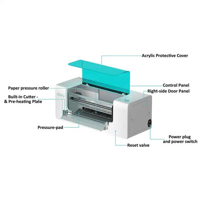
| 1. Acrylic Protective Cover | Equipment protective cover. Blocks foreign objects from falling into the machine and prevents accidental contact with internal moving components during operation for safety protection. |
| 2. Control Panel | Human‑machine interaction control panel. Used to set print parameters, view device status, display error alerts and execute machine operation commands. |
| 3. Power plug and power switch | The power plug connects to mains power; the power switch controls power‑on / power‑off for the whole unit to start and stop the device. |
| 4. Right-side door panel | Machine side service door. Open it for consumable replacement and internal‑component maintenance. Keep closed in daily use to protect internal circuits and mechanical structures. |
| 5. Reset valve | Open this hatch to observe real‑time initialization alignment and sealing status of printhead and ink stack. |
| 6. Built-in Cutter -& Pre-heating Plate | Pre‑heating plate preheats the print film to improve coating adhesion. Built‑in cutter automatically cuts finished DTF film. |
| 7. Pressure‑pad | The pressure‑pad holds the DTF film flat against the operating platform. It prevents film curling, lifting and shifting during printing, to avoid misalignment, ghosting and ink smudges. |
| 8. Paper pressure roller | The paper pressure roller grips and feeds the DTF film. It keeps the media stable during printing to prevent shifting and ghosting. |
¶ Rear View
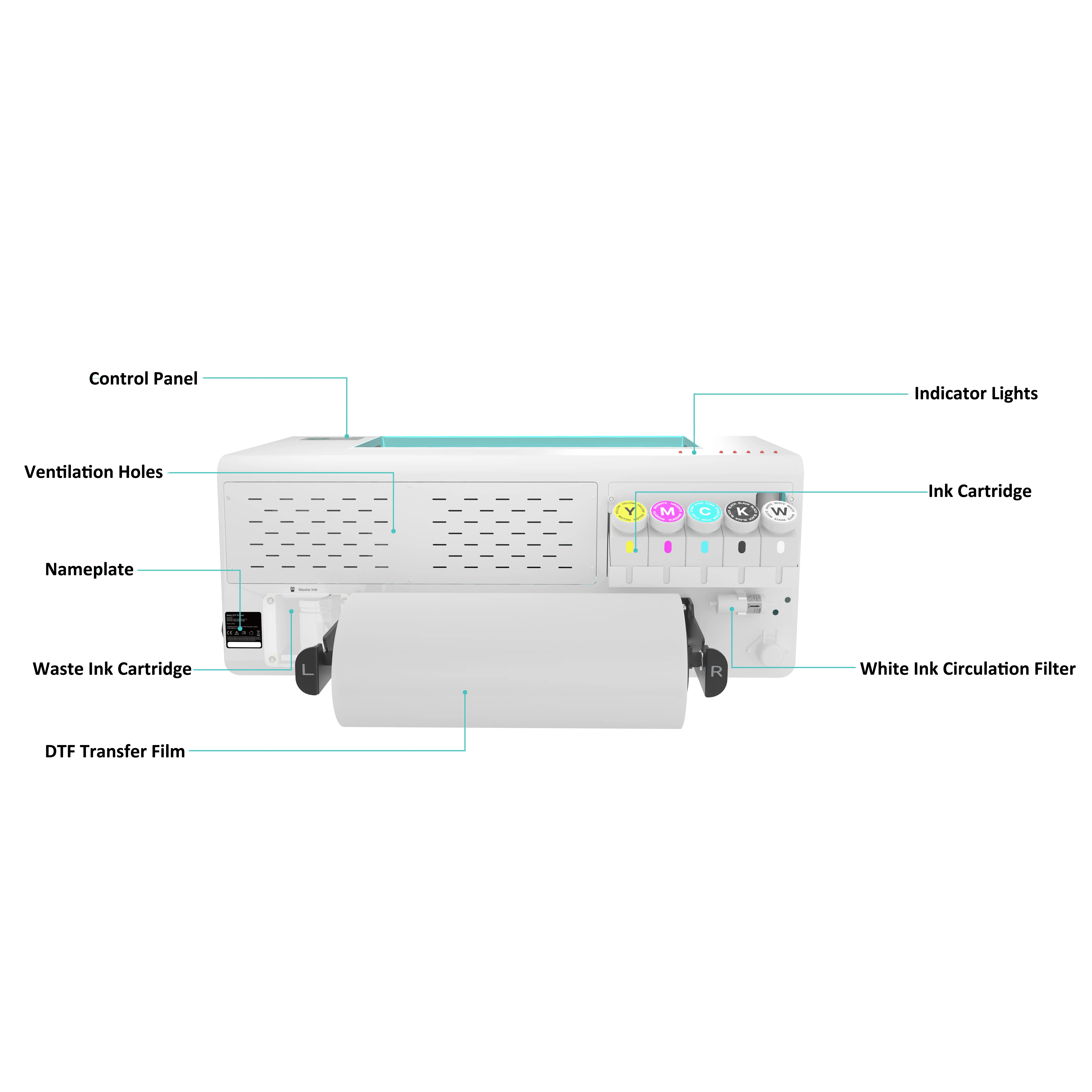
| 1. Control Panel | Human‑machine interaction control panel. Used to set print parameters, view device status, display error alerts and execute machine operation commands. |
| 2. Ventilation holes | Dissipate heat generated during machine operation to prevent overheating and damage to internal components. |
| 3.Nameplate | Displays product information including model, rated parameters and serial number. |
| 4.DTF Transfer Film | Printing medium that carries printed patterns for subsequent heat transfer onto fabrics. |
| 5.Indicator Lights | Indicate machine status via light color and flashing: standby, running, error and ink‑out alerts. |
| 6.Ink Cartridge | Store each color ink and supply CMYK & white ink for the printing system. |
| 7.Circulation Filter | Filters impurities in white ink, avoids printhead clogging caused by white‑ink sediment and ensures smooth circulation. |
| 8.Waste Ink Cartridge | Collects waste ink generated during printhead cleaning, stores waste liquid to prevent ink overflow and contamination. |
¶ HP1
¶ Front View
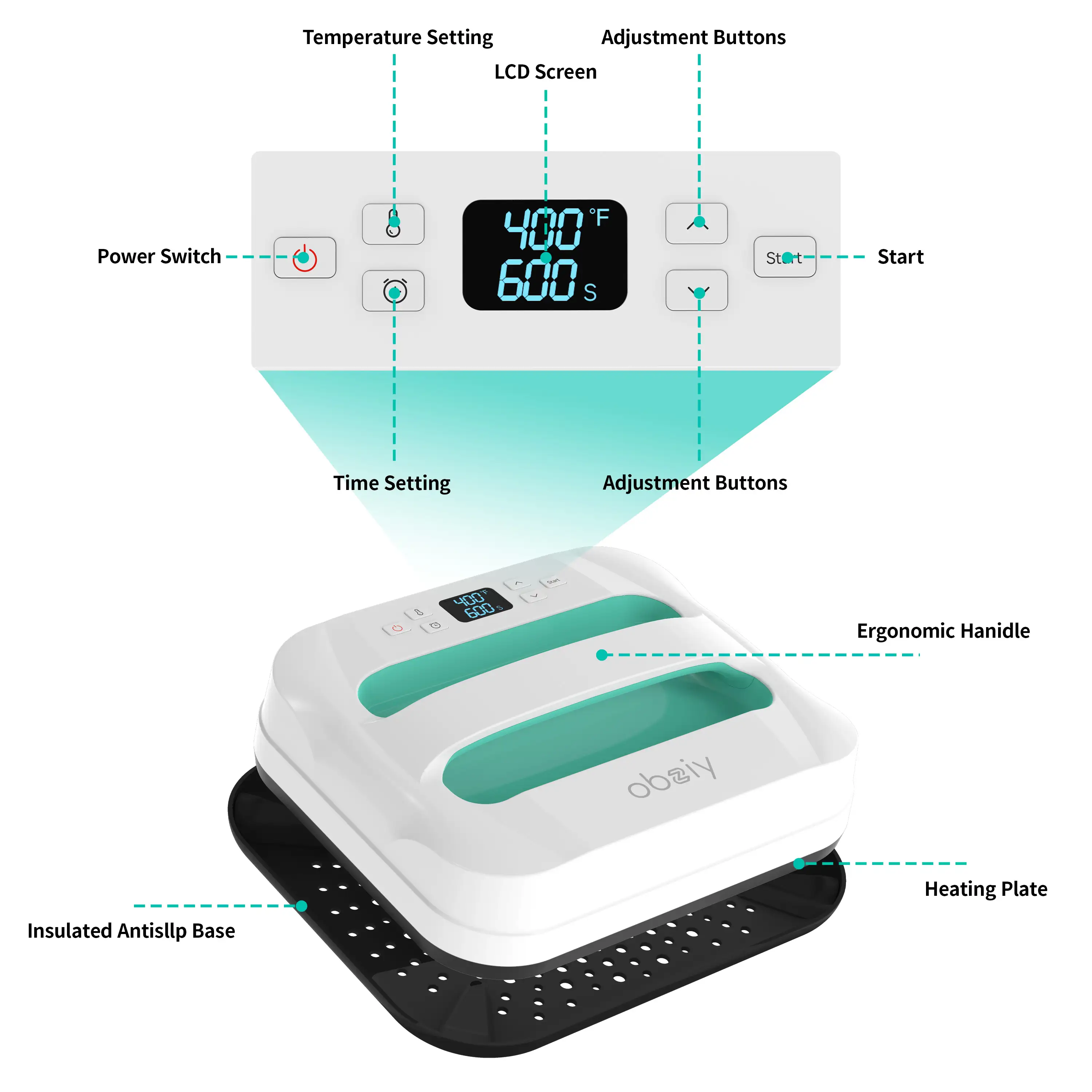
| 1.Ergonomic Handle | For opening and closing the heat press lid, convenient for lifting and moving the unit. |
| 2. Heating Plate | Provides high temperature for heat‑transfer curing, direct contact with transfer materials. |
| 3.Insulated Antislip Base | Heat‑resistant and anti‑slip base, prevents unit slipping during operation and protects work surface. |
| 4. Power Switch | Main power button to turn the device on and off. |
| 5. emperature Setting Button | Used to set the target heat‑press working temperature. |
| 6. Time Setting Button | Used to set heat‑press working countdown time. |
| 7. LCD Screen | Displays real‑time temperature, remaining time and machine working status. |
| 8. Up Adjustment Button | Increase value of temperature or time parameters. |
| 9. Down Adjustment Button | Decrease the value of temperature or time parameters. |
| 10. Start Button | Confirm parameters and start the heat‑press workflow. |
¶ HP1Mini
¶ Front View
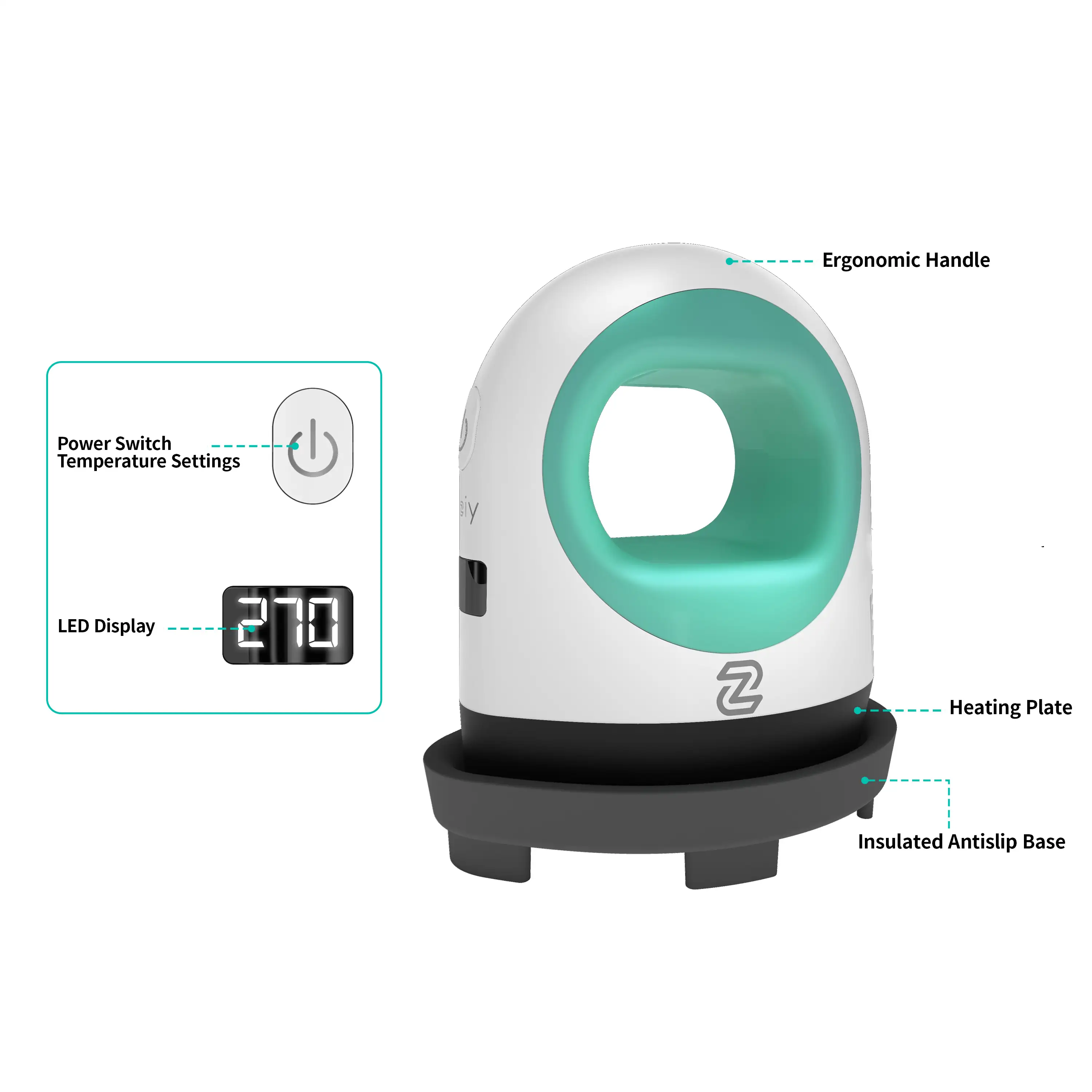
| 1. Ergonomic Handle | For opening and closing the heat press lid, convenient for lifting and moving the unit. |
| 2. Heating Plate | Provides high temperature for heat‑transfer curing, direct contact with transfer materials. |
| 3. Insulated Antislip Base | Heat‑resistant and anti‑slip base, prevents unit slipping during operation and protects work surface. |
| 4. Power Switch | Main power button to turn the device on and off. |
| 5. LCD Screen | Displays real‑time temperature, remaining time and machine working status. |
¶ Auto HP1
¶ Front view
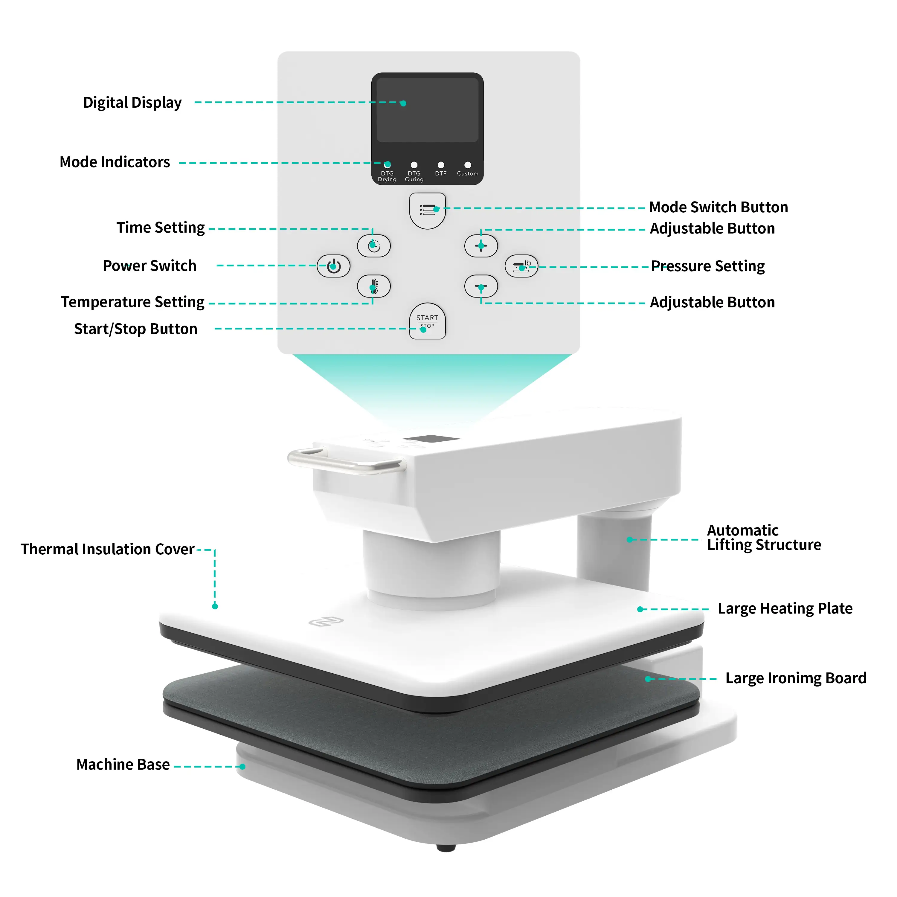
| 1. Digital Screen Display | Displays real‑time temperature, time, pressure, machine mode and working status. |
| 2. Mode Indicators | Visually indicates the current working mode of the machine. |
| 3. Mode Switch Button | Switch between different working modes of the unit. |
| 4. Time Setting Button | Set the working countdown time for heat‑press tasks. |
| 5. Power Switch | Main power button for powering the device on and off. |
| 6.Temperature Setting Button | Set target operating temperature for heat pressing. |
| 7. Adjustable Button(+) | Increase the value of temperature, time or pressure parameters. |
| 8. Adjustable Button(-) | Decrease the value of temperature, time or pressure parameters. |
| 9. Pressure Setting Button | Adjust the pressure level for heat‑press operations. |
| 10. Start/Stop Button | Start the heat‑press procedure or stop an ongoing task. |
| 11. Thermal Insulation Cover | Thermal protective cover to prevent burns from high‑temperature components. |
| 12. Automatic Lifting Structure | Automatically lifts the heating head after pressing, no manual lid lifting required. |
| 13. Large Heating Plate | High‑temperature heating plate, direct contact with materials to complete heat transfer. |
| 14. Large Ironing Board | Supports transfer materials, buffers pressure and protects consumables. |
| 15. Machine Base | Main machine base, stabilizes the whole unit and protects work surface. |